

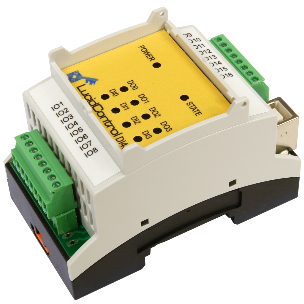
- 16 analog and digital IO channels
- HTTPS, Modbus TCP/IP, MQTT, FTP
- SSL/TLS secured
- Data logging function
- Compatible with LucidControl software
- DIN-Rail enclosure
- Multi-Protocol

LucidControl USB IO Modules
- Data acquisition and control
- Cost effective and flexible
- Platform independent
- Windows® and Linux
- Compatible with Raspberry Pi
- Clippable on DIN-Rail
- Industrial & home automation
USB Digital Input Output Module
LucidControl Product Series
- 4 insulated digital input channels
- Counters, filters, edge detectors
- Pulse width modulation and timers
- 4 solid-state-relay output channels

USB Digital Input Module
LucidControl Product Series
- 4 / 8 digital input channels
- For 5V, 10V and 24V signals
- Opto insulated contacts
- Counters and edge detectors

USB Digital Output Module
LucidControl Product Series
- Opto insulated option
- 4 / 8 digital output channels
- Relay module option
- Pulse width modulation and timers
- Switching and power control

USB Analog Input Module
LucidControl Product Series
- Measurement range options
- 4 / 8 analog input channels
- e.g. 0-10 V or 0-20mA
- 14 bit resolution
- Acquisition of sensor signals

USB Analog Output Module
LucidControl Product Series
- 4 analog output channels
- Output range options
- e.g. 0 - 10 V or 4 - 20 mA
- 12 bit resolution
- 4 - 20 mA current interfaces
USB RTD Input Module
LucidControl Product Series
- 4 / 8 Pt1000 / Pt100 RTD channels
- Temperature range: +/- 180 °C, 360 °C
- 0.1 °C resolution
- Heat control applications
- Logging of temperatures
Outdated Information
This online document might be outdated. Please see the LucidControl USB RTD Input Module PDF documentation instead.
3 Module Operation

Fig. 3-1 RTD Input Channel Data Acquisition
The acquisition circuit sources the RTD with a constant current and measures the voltage drop over the RTD which is proportional to the resistance and represents a temperature.
Fig. 3-1 explains the measurement procedure in Standard Acquisition Mode. The diagram shows two active RTD channels in order to keep the diagram simple.
The blue lines are related to measurement channel 1, the red lines to measurement channel 2.
It can be seen that the multiplexer is set to the appropriate input which sources the connected RTD with a constant current. Only one RTD is sourced with current at a given time. All active RTDs are processed subsequently by waiting the time TScan. After an input channel was selected the input waits for a configurable time TSetup until the resistance of the RTD is stable and ready for conversion. TSetup and TScan can be configured for each channel but it must be ensured that the times are chosen in a way that the scheduler is able to process each active channel.
Decreasing the values to not realistic timing may cause invalid values or may skip channels completely. The default values given in the table should only be changed if faster measurements are necessary or if the measured result is not stable.
| Parameter | Time |
|---|---|
| TScan | 500 ms |
| TSetup | 50 ms |
3.1 Data Acquisition Modes
3.1.1 Inactive Mode
In Inactive Mode the RTD measurement is disabled and the channel is skipped.
3.1.2 Standard Acquisition Mode
In Standard Acquisition Mode the RTD the inputs are measured as configured.
3.2 Input Calibration
The LucidControl RT4 module measures analog signals (more precisely voltages) which are captured, conditioned and converted to digital values.
In contradiction to logical signals, where obviously only two states LOW or HIGH are possible, all analog voltages within a specified range are converted to their representing digital value.
The signal conditioning which is part of the measurement circuit contains components which are not free from tolerances (e.g. offset voltages of amplifier). These have to be compensated in order to measure a correct value.
The calibration functions of the RT4 module which are described in the following compensate these measurement tolerances.
Note
All modules are calibrated before shipping and it is not necessary to re-calibrate a new module nor is it necessary to calibrate it regularly!
3.2.1 Full Calibration
The full input calibration consists of two measurements:
- Open Input Calibration where the IO terminals are left unconnected
- Short Input Calibration where the IO terminals are shortcut
On full input calibration both, the open and the short calibration must be executed.
After full input calibration has finished the module is able to measure all values with the specified accuracy.
3.2.1.1 Short Input Calibration
For short input calibration the inputs must be shortcut as it is shown in Fig. 3.2.1.1-1. After creating a shortcut e.g. by connecting the terminals 1 and 2 of input channel 0 the short input calibration can be executed by using the LucidIoCtrl command line tool. For detailed information see section 3.2.3.
Example
The short input calibration should be done for channel 0 and the result should be stored for further usage.
LucidIoCtrl –dCOM1 –c0 –a --short –p –-quiet [ENTER]
In combination with the I/O Calibration command (-a) the short input calibration is specified (–short). Passing Parameter –quiet causes LucidIoCtrl to skip user confirmation before the command is started. Using Parameter –p makes the calibration setting persistent so that is used after a restart of the module.
After short input calibration for channel 0 has finished the remaining input channels can be calibrated the same way.
3.2.1.2 Open Input Calibration
For open input calibration the input terminals must be left unconnected. In order to execute the open input calibration the LucidIoCtrl command line tool can be used. For detailed information see section 3.2.3.
Example
The open input calibration should be done for channel 0 and the result should be stored for further usage.
LucidIoCtrl –dCOM1 –c0 –a --open –p –-quiet [ENTER]>
In combination with the I/O Calibration command (-a) the open input calibration is specified (–open). Passing Parameter –quiet causes LucidIoCtrl to skip user confirmation before the command is started. Using Parameter –p makes the calibration setting persistent so that is used after a restart of the module.
After open input calibration for channel 0 has finished the remaining input channels can be calibrated the same way.
3.2.2 Offset Compensation
In order to compensate the offset of an input channel the Parameter inRtOffset can be used.
This parameter allows configuring an offset resistance in 0.1 Ω steps which is added to the measured resistor. Since inRtOffset can also be a negative value, compensation in both directions to higher or lower values is possible.
For the RT4 module a 0 offset compensation can be made by connecting a load resistor.
Measured Resistance: R= RM + ROffset
Whereas R, RM and ROffset are values in 0.1 Ω resolution.
Since the temperature is approx. proportional T[℃] ~ R/10 * 0.256 [℃/Ω] the value RM changes the resulting temperature by approx. 0.0256 [℃/Digit].
Example
When connecting a 1000 Ω resistor to the input channel 0 the resulting temperature should be exactly 0 °C. In this example it is +0.5 °C caused by outer influences e.g. the RTD itself. This offset value is compensated in the following.
With the equations above it can be calculated that the deviation of +0.5 °C results in an offset correction value of -19.53 (rounded -20, which means -2.0 Ω)
The following function call adjusts the measured value to the load of 1000 Ω representing a value close to 0°C and stores the setting:
LucidIoCtrl –dCOM1 –c0 –sinRtOffset=-20 –p [ENTER]
3.3 Commands
Accessing inputs and outputs is a very common task which is mostly identical for all LucidControl modules. For this task input modules provide the commands GetIo for reading of a single value and GetIoGroup for reading of a group of values of the same type.
For more comprehensive information covering reading and writing of inputs and outputs please see this sections:
- LucidIoCtrl Commandline Tool (Read Command)
- General Lucid Control Documentation (Implemented Commands)
The following sections describe the commands supported by the RT4 module in detail.
3.3.1 GetIo
This command reads the value of a RTD input.
Please see also the General LucidControl documentation for more information.
| Command | GetIo | Access | Read | ||||
|---|---|---|---|---|---|---|---|
| Opcode | 0x46 | ||||||
| LucidIoControl Command Line Tool | |||||||
| Call (-tV) | LucidIoCtrl –d[COMx] –c[Channels] –tT –r |
||||||
| Return |
CHn:TT
|
||||||
| Call (-tA) | LucidIoCtrl –d[COMx] –c[Channels] –tR –r |
||||||
| Return |
CHn:DD
|
||||||
Request Frame
| OPC | P1 | P2 | LEN |
|---|---|---|---|
| 0x46 | Channel | Value Type | 0 |
| Value | Description | ||||||||||||
|---|---|---|---|---|---|---|---|---|---|---|---|---|---|
| Channel | Number of input channel (Range: 0 ~ 3) | ||||||||||||
| Value Type |
|
Response Frame
| Status | LEN | Data Field |
|---|---|---|
| Status | Size | Value |
In case of successful execution the command returns the value of the specified channel number.
In the case of an error the command returns Execution Status Code.
LucidIoCtrl Command Line Tool Example
Read temperature from input channel 0:
LucidIoCtrl –dCOM4 –c0 –tT -r [ENTER]

->	CH0:100.200
Read the corresponding resistance of the same input
LucidIoCtrl –dCOM4 –c0 –tR -r [ENTER]

->	CH0:1385.8
Shortcut and Wire Break Detector:
The module is able to detect RTD shortcut and wire breaks in the connection cable. In the case of a wire break is detected the command returns ERR_OPEN. In the case that a shortcut is detected the command returns ERR_SHORT.
Note
When using the LucidIoCtrl command line tool the distinction between GetIo and GetIoGroup commands is not necessary since the program handles this automatically.
3.3.2 GetIoGroup
This command reads the values of a group of RTD inputs of the same Value Type. See also For more information about reading of analog inputs.
Please see also the General LucidControl documentation for more information.
| Command | GetIoGroup | Access | Read | ||||
|---|---|---|---|---|---|---|---|
| Opcode | 0x48 | ||||||
| LucidIoControl Command Line Tool | |||||||
| Call (-tV) | LucidIoCtrl –d[COMx] –c[Channels] –tT –rChannels Comma separated list of channels e.g. –c0,1,3 |
||||||
| Return |
CHn:TT
|
||||||
| Call (-tA) | LucidIoCtrl –d[COMx] –c[Channels] –tR –rChannels Comma separated list of channels e.g. –c0,1,3 |
||||||
| Return |
CHn:DD
|
||||||
Request Frame
| OPC | P1 | P2 | LEN |
|---|---|---|---|
| 0x48 | Channel Mask |
Value Type | 0 |
| Value | Description | |||||||||||||||
|---|---|---|---|---|---|---|---|---|---|---|---|---|---|---|---|---|
| Channel Mask | Specifies the output channels to access
Values can be bitwise combined |
|||||||||||||||
| Value Type |
|
Response Frame
| Status | LEN | Data Field |
|---|---|---|
| Status | Size | Value(s) |
In case of successful execution the command returns the value of the specified channels.
In the case of an error the command returns Execution Status Code.
Example of GetIoGroup Request
This request frame reads temperatures from input channels 0 and 1
Request Frame
| OPC | P1 | P2 | LEN |
|---|---|---|---|
| 0x48 | 0x03 | 0x41 | 0x00 |
Channel Mask (P1) = 0x01 OR 0x02 = 0x03
Response Frame
For input channel 0 = 50 °C and input channel 1 = -25° C
Values in Data Field are in ascending order Channel 0 and Channel 1.
| Header Field | Data Field | ||||||||
|---|---|---|---|---|---|---|---|---|---|
| Status | LEN | Value Channel 0 | Value Channel 1 | ||||||
| 0x00 | 0x08 | 0x88 | 0x13 | 0x00 | 0x00 | 0x3C | 0xF6 | 0xFF | 0xFF |
LucidIoCtrl Command Line Tool Example
Read temperatures from all input channels:
LucidIoCtrl –dCOM4 –c0,1,2,3 –tT –r [ENTER]

->	CH0:100.000  CH1:0.500  CH2:-100.300  CH3:78.250
Read temperatures form all input channels:
LucidIoCtrl –dCOM4 –c0,1,2,3 –tT –r [ENTER]

->	CH0:100.000  CH1:0.500  CH2:ERR_SHORT  CH3:ERR_OPEN
In this case the RTD connected to input channel 2 is shortcut and no RTD is connected to input channel 2.
3.3.3 CalibrateIO
This command performs the full input calibration.
| Command | CalibrateIo | Access | – |
|---|---|---|---|
| Opcode | 0x52 | ||
| LucidIoControl Command Line Tool | |||
| Call | LucidIoCtrl –d[COMx] –c[Channel] –a {--quiet} {–p} {--short} {--open} |
||
Request Frame
| OPC | P1 | P2 | LEN |
|---|---|---|---|
| 0x52 | Channel | Option | 0x00 |
| Value | Description | |||||||||
|---|---|---|---|---|---|---|---|---|---|---|
| Channel | Number of input channel (Range: 0 ~ 3) | |||||||||
| Option |
Controlling of calibration function
|
Response Frame
| Status | LEN |
|---|---|
| Status | 0x00 |
The command does not return any data.
In the case of an error the command returns Execution Status Code.
3.4 Parameter
LucidControl modules allow configuration by a set of System Configuration Parameters and IO Configuration Parameters.
The Parameters are accessible by using the SetParam command and GetParam command which are described the genreral LucidControl documentation.
3.4.1 inRtValue
This IO Configuration Parameter contains the measured resistance value with a resolution of 0.1 Ω.
| Parameter | inRtValue | Access | Read |
|---|---|---|---|
| Address | 0x1000 | ||
| Values | Measured Resistance in 0.1 Ω | ||
| Default Value | 0x00 | Parameter Type | 2 Bytes unsigned |
| LucidIoControl Command Line Tool | |||
| ParameterName | inRtValue | Parameter Values | 0 ~ 6,553.5 Ω |
| Call (Get) | LucidIoCtrl –d[COMx] –c[Channel] –ginRtValue | ||
LucidIoCtrl Command Line Tool Example
Read value parameter of input channel 0:
LucidIoCtrl –dCOM4 –c0 –ginRtValue [ENTER]

inDiValue=100
The measured value of 10.0 Ω is returned.
Note:
For normal operation is recommended to use the function GetIo in order to read the input value. The parameter provides the resistance value only.
3.4.2 inRtMode
This IO Configuration Parameter configures the operation mode of the input.
| Parameter | inRtMode | Access | Read / Write | ||||||
|---|---|---|---|---|---|---|---|---|---|
| Address | 0x1100 | ||||||||
| Values | Input Mode
|
||||||||
| Default Value | 0x00 | Parameter Type | 1 Byte unsigned | ||||||
| LucidIoControl Command Line Tool | |||||||||
| ParameterName | inRtMode | Parameter Values | inactive / standard | ||||||
| Call (Set) | LucidIoCtrl –d[COMx] –c[Channel] –sinRtMode=[Mode] {-p} {--default} | ||||||||
| Call (Get) | LucidIoCtrl –d[COMx] –c[Channel] –ginRtMode | ||||||||
LucidIoCtrl Command Line Tool Example
Set operation mode of input channel 0 to standard mode and make the setting persistent.
LucidIoCtrl –dCOM4 –c0 –sinRtMode=standard –p [ENTER]
Read the operation mode of input channel 0
LucidIoCtrl –dCOM4 –c0 –ginRtMode [ENTER]

->  inRtMode=standard
3.4.3 inRtScanTime
This IO Configuration Parameter specifies the scan time TScan of the RTD input channel.
| Parameter | inRtScanTime | Access | Read / Write |
|---|---|---|---|
| Address | 0x1111 | ||
| Values | TScan in ms (milli seconds) 50 ms ≤ TScan ≤ 10 s |
||
| Default Value | 500 (500 ms) | Parameter Type | 2 Bytes unsigned |
| LucidIoControl Command Line Tool | |||
| ParameterName | inAnScanTime | Parameter Values | TScan [ms] |
| Call (Set) | LucidIoCtrl –d[COMx] –c[Channel] –sinRtScanTime=[Time] {-p} {--default} | ||
| Call (Get) | LucidIoCtrl –d[COMx] –c[Channel] –ginRtScanTime | ||
LucidIoCtrl Command Line Tool Example
Set TScan of input channel 0 to 250 ms and make the setting persistent.
LucidIoCtrl –dCOM4 –c0 –sinRtScanTime=250 –p [ENTER]
Read TScan parameter of input channel 0
LucidIoCtrl –dCOM4 –c0 –ginRtScanTime [ENTER]

-> inRtScanTime=250
3.4.4 inRtSetupTime
This IO Configuration Parameter configures the input channel setup time TSetup
Parameter
inRtSetupTime
Access
Read / Write
Address
0x1112
Values
TScan in ms (milli seconds)
5 ms ≤ TSetup ≤ 1 s
Default Value
50 (50 ms)
Parameter Type
2 Bytes unsigned
LucidIoControl Command Line Tool
ParameterName
inAnScanTime
Parameter Values
TScan [ms]
Call (Set)
LucidIoCtrl –d[COMx] –c[Channel] –sinRtSetupTime=[Time] {-p} {--default}
Call (Get)
LucidIoCtrl –d[COMx] –c[Channel] –ginRtSetupTime
LucidIoCtrl Command Line Tool Example
Set TSetup of input channel 0 to 25 ms and make the setting persistent.
LucidIoCtrl –dCOM4 –c0 –sinRtSetupTime=25 –p [ENTER]
Read TScan parameter of input channel 0
LucidIoCtrl –dCOM4 –c0 –ginRtSetupTime [ENTER]

->  inRtSetupTime=25
3.4.5 inRtOffset
This IO Configuration Parameter configures the Input Offset Compensation value which is described in section 3.1.2.
| Parameter | inRtOffset | Access | Read / Write |
|---|---|---|---|
| Address | 0x1120 | ||
| Values | Offset Compensation in 0.1 Ω steps (-1,000 Ω ~ 1,000 Ω) -10,000 ~ 10,000 |
||
| Default Value | 0 | Parameter Type | 2 Bytes signed |
| LucidIoControl Command Line Tool | |||
| ParameterName | inRtOffset | Parameter Values | Resistance [0.1 Ω] |
| Call (Set) | LucidIoCtrl –d[COMx] –c[Channel] –sinRtOffset=[Offset] {-p} {--default} | ||
| Call (Get) | LucidIoCtrl –d[COMx] –c[Channel] –ginRtOffset | ||
LucidIoCtrl Command Line Tool Example
Set Input Offset Compensation value of input channel 0 to -2 Ω and make the setting persistent.
LucidIoCtrl –dCOM4 –c0 –sinRtOffset=-20 –p [ENTER]
Read Input Offset Compensation value
LucidIoCtrl –dCOM4 –c0 –ginRtOffset [ENTER]

->  inRtOffset=20
3.4.6 inRtCalUm
This IO Configuration Parameter configures the full calibration value “UM” which is described in section 3.1.1. The value does not have a unit and even if it possible it is not recommended to change this value manually.
| Parameter | inRtCalUm | Access | Read / Write |
|---|---|---|---|
| Address | 0x1130 | ||
| Values | Full Calibration Value UM | ||
| Default Value | 0 | Parameter Type | 2 Bytes unsigned |
| LucidIoControl Command Line Tool | |||
| ParameterName | inRtCalUm | Parameter Values | 0 ~ 65,535 |
| Call (Set) | LucidIoCtrl –d[COMx] –c[Channel] –sinRtCalUm=[Value] {-p} {--default} | ||
| Call (Get) | LucidIoCtrl –d[COMx] –c[Channel] –ginRtCalUm | ||
LucidIoCtrl Command Line Tool Example
Read Full Calibration Value UM of input channel 0
LucidIoCtrl –dCOM4 –c0 –ginRtCalUm [ENTER]

-> inRtCalUm=760
3.4.7 inRtCalUrs
This IO Configuration Parameter configures the full calibration value “URS” which is described in section 3.1.1. The value does not have a unit and even if it possible it is not recommended to change this value manually.
| Parameter | inRtCalUrs | Access | Read / Write |
|---|---|---|---|
| Address | 0x1131 | ||
| Values | Full Calibration Value URS | ||
| Default Value | 0 | Parameter Type | 2 Bytes signed |
| LucidIoControl Command Line Tool | |||
| ParameterName | inRtCalUrs | Parameter Values | -32,768 ~ 32,767 |
| Call (Set) | LucidIoCtrl –d[COMx] –c[Channel] –sinRtCalUrs=[Value] {-p} {--default} | ||
| Call (Get) | LucidIoCtrl –d[COMx] –c[Channel] –ginRtCalUrs | ||
LucidIoCtrl Command Line Tool Example
Read Full Calibration Value URS of input channel 0
LucidIoCtrl –dCOM4 –c0 –ginRtCalUrs [ENTER]

->  inRtCalUrs=760
| Previous | Top | Next |
|---|---|---|
| 2 Setup and Installation | LucidControl RTD Input USB Module Content | 4 Specification |
Leave a Reply
Want to join the discussion?Feel free to contribute!