

- 16 analog and digital IO channels
- HTTPS, Modbus TCP/IP, MQTT, FTP
- SSL/TLS secured
- Data logging function
- Compatible with LucidControl software
- DIN-Rail enclosure
- Multi-Protocol

LucidControl USB IO Modules
- Data acquisition and control
- Cost effective and flexible
- Platform independent
- Windows® and Linux
- Compatible with Raspberry Pi
- Clippable on DIN-Rail
- Industrial & home automation
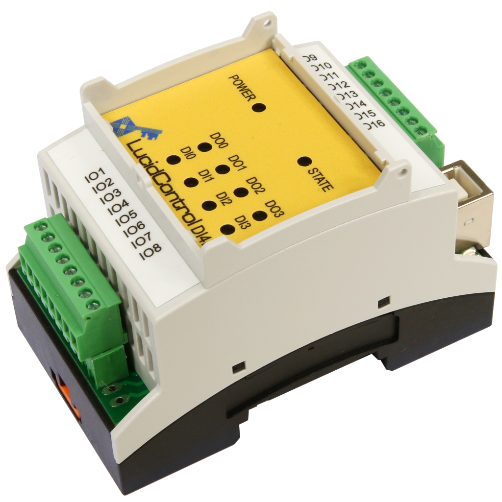
USB Digital Input Output Module
LucidControl Product Series
- 4 insulated digital input channels
- Counters, filters, edge detectors
- Pulse width modulation and timers
- 4 solid-state-relay output channels

USB Digital Input Module
LucidControl Product Series
- 4 / 8 digital input channels
- For 5V, 10V and 24V signals
- Opto insulated contacts
- Counters and edge detectors

USB Digital Output Module
LucidControl Product Series
- Opto insulated option
- 4 / 8 digital output channels
- Relay module option
- Pulse width modulation and timers
- Switching and power control

USB Analog Input Module
LucidControl Product Series
- Measurement range options
- 4 / 8 analog input channels
- e.g. 0-10 V or 0-20mA
- 14 bit resolution
- Acquisition of sensor signals

USB Analog Output Module
LucidControl Product Series
- 4 analog output channels
- Output range options
- e.g. 0 - 10 V or 4 - 20 mA
- 12 bit resolution
- 4 - 20 mA current interfaces
USB RTD Input Module
LucidControl Product Series
- 4 / 8 Pt1000 / Pt100 RTD channels
- Temperature range: +/- 180 °C, 360 °C
- 0.1 °C resolution
- Heat control applications
- Logging of temperatures
Outdated Information
This online document might be outdated. Please see the LucidControl Product Series PDF documentation instead.
3 LucidIoCtrl Command Line Tool (LCLT)
3.1 Introduction
The LucidIoCtrl Command Line Tool gives easy and complete access to all functions of LucidControl.
It is most simple zo invoke LCLT is by opening a console or logging in remotely by SSH. LCLT gives immediately access to all LucidControl modules connected to the host computer.
The tool was designed in order to provide a solution which runs standalone without depending on any library and which is available for all architectures. The application runs under Microsoft Windows® and Linux. Copying the executable file to the host computer is all needed to do.
Moreover command line tools can be integrated into nearly all applications. It does not matter if PHP, Python, C#, Java or any other programming language is used. All modern programming languages have the ability to run a console application with parameters and to evaluate their output.
With this program the user gets a lightweight Application Programming Interface (API) for LucidControl which can be used even without programming knowledge by entering the commands to the shell.
Let’s take the following example
It is assumed that the LucidControl module is connected to COM4.
The output channel 0 of a digital output module should be set.
While running Microsoft Windows® prompt entering the line:
LucidCtrl –dCOM4 –c0 –w1 –tL [ENTER]
Or by entering this to the Linux shell when LucidControl is connected to /dev/lucidIoKitchen:
./LucidCtrl –d/dev/lucidIoKitchen –c0 –w1 –tL [ENTER]
Both examples set the output to 1.
For the moment this should be enough to demonstrate the simplicity of LucidIoCtrl. The details of the commands are explained in the following sections.
Moreover the program can also be used for web applications running e.g. in Apache web server. PHP or Java applications can execute LucidIoCtrl and set or reset an output by clicking onto a button.
3.2 LCLT Arguments
LucidIoCtrl is controlled by arguments succeeding the program name as it is usual for command line tools. These arguments are split into two groups:
3.2.1 Command Arguments
Command Arguments specify the command that should be executed. Exactly one command argument must be passed when calling LCLT.
| Argument | Description |
|---|---|
| -a | I/O Calibration |
| -g | Read Parameter |
| -i | Identify Device |
| -r | Read I/O Channel(s) |
| -s | Write Parameter |
| -w | Write I/O Channel(s) |
The table shows all available Command Arguments with their short description. They are described in this section.
3.2.1.1 –write, -w
The Write command assigns values to output cannels.
Function call
./LucidIoCtrl –dDEVICE –wValue(s) -cChannel(s) –tValueType [ENTER]
Examples
This command sets output channel 0 (-c0) to 0 (-w0). The -tL argument specifies that a digital value is written which can be either 0 or 1. This is the typical function call for setting a digital output:
./LucidIoCtrl –d/dev/LucidIo –w0 -c1 –tL [ENTER]
This command sets the analog output 2 (-c2) to a voltage (-tV) of -5.000 V (-w-5.000):
./LucidIoCtrl –d/dev/LucidIo –w-5.000 –c2 –tV [ENTER]
This command sets the analog output 3 (-c3) to a current (-tC) of 2.5 mA (-w2.500):
./LucidIoCtrl –d/dev/LucidIo –w2.500 –c3 –tC [ENTER]
This example shows that it is also possible to set the values of multiple outputs by one single function call:
./LucidIoCtrl –dLucidIo –w2.500,5.000,1.250 –c1,2,0 –tV [ENTER]
The function call sets the analog output 0 to 1.250 V, output 1 auf 2.500V and output 2 to 5.000 V. It must be noted that channels and values must be ordered the same way.
The Write command is able to access different value types like logical, counters or analog voltages. Please see Option Argument Type for further information about value types and see the module specific documentation on information about supported value types.
In the case of successful execution, the Write command finishes without returning information (on the output console). In the case of error please see section Return Values for more information.
3.2.1.2 –read, -r
The Read command returns the input values of inputs. It can only be used to read the current state of outputs. The returned value is formatted accordingly to the requested value type.
Function call
./LucidCtrl –dDEVICE –r -cChannel(s) –tType [ENTER]
Examples
This example reads channel 1 (-c1) of a digital input. It can also be used in order to read the state of a digital output:
 ./LucidCtrl –d/dev/LucidIo –r -c1 –tL [ENTER]

-> CH1:00
The Read command returns values in a formatted form. In the example above the digital input channel 1 (CH1) is not set.
The following example reads analog voltages from the channels 0, 1 and 2. The returned values are in ascending order:
 ./LucidCtrl –d/dev/LucidIo –r –c2,0,1 –tV [ENTER]

-> CH0:1.250   CH1:2.500   CH2:5.000
The Read command is able to access different value types like logical, counters or analog voltages. Please see Option Argument Type for further information about value types and see the module specific documentation on information about supported value types.
In the case of successful execution, the Read command returns the requested values. In case of error please see section 3.3 for more information. In the case of error please see section Return Values for more information.
3.2.1.3 –setparam, -s
The Set Parameter command sets Configuration Parameters of the LucidControl USB IO Module.
Function call
./LucidCtrl –dDEVICE {-cChannel(s)} –sParameter=Value {-p} {-y} [ENTER]
In the case that the Parameter is related to an input or output, the channel has to be passed with the Option Argument –c.
With the Option Argument –p the setting can be made persistent so that it is loaded after the restart of the module (see section Persistent).
The Option Argument –y sets the parameter back to the default value (see section Default).
The Option Arguments –p and –y can be combined in order to restore the default setting permanently.
Examples
This example enabled “Blink Mode”. In this mode the status LED of LucidControl blinks once on an incomming command indicating the ongoing communication:
./LucidCtrl –d/dev/LucidIo –ssysSignalCmd=on [ENTER]
This example configures the digital input channel 0 for Reflect mode:
./LucidCtrl –d/dev/LucidIo –c0 –sinDiMode=reflect [ENTER]
A detailed description of all parameters supported by the module and its inputs or outputs can be found in the “Parameters” section of the module specific user manual.
In the case of successful execution, the Set Parameter command finishes without returning information (on the output console). In the case of error please see section Return Values for more information.
3.2.1.4 –getparam, -g
The Get Parameter command reads Configuration Parameters of the LucidControl USB IO Module.
Function call
./LucidCtrl –dDEVICE {-cChannel(s)} –gParameter [ENTER]

-> Parameter=Value
Example
This example returns the operation mode of digital input channel 0:
./LucidCtrl –d/dev/LucidIo –c0 –ginDiMode [ENTER]

-> inDiMode=reflect
A detailed description of all parameters supported by a module and its inputs or outputs can be found in the “Parameters” section of the module specific user manual.
In the case of successful execution, the Get Parameter command returns the parameter name and the parameter value.
In the case of error please see section Return Values for more information.
3.2.1.5 –calibrate, -a
The Calibrate IO command starts calibration of LucidControl.
Some LucidControl USB IO Modules needs to be calibrated. This means that inputs or outputs of a module are adjusted in order to generate most accurate results.
The calibration procedure depends on the type of module. More information can be found in the module specific user manual.
Function call
./LucidCtrl –dDEVICE {-cChannel(s)} –a {-q} {--short} {--open} [ENTER]
EXECUTE I/O CALIBRATION FOR CHANNEL … ?
In the case that the optional –q Option Argument is used the Calibrate IO command is executed immediately without asking for user confirmation. Otherwise the application requires confirmation of the user before it continues with calibration.
When a specific channel has to be calibrated it has to be specified by the –c Option Argument. Most modules need this parameter.
Example
This example calibrates the input channel 0 of e.g. an analog input module without user confirmation:
./LucidCtrl –dLucidIo –c0 –a -q [ENTER]
In the case of successful execution, the Calibrate IO command finishes without retuning further information.
In the case of error please see section Return Values for more information.
3.2.1.6 –identify, -i
The identify command returns general information of a module.
Function call
./LucidCtrl –dDEVICE -i [ENTER]

->  DEVICE CLASS:       xxxx          (Device Class Description)

->  DEVICE TYPE:        1000          (Device Type Description)

->  SERIAL NUMBER:      xxxxxxxx

->  FIRMWARE REVISION:  xxxx

->  HARDWARE REVISION:  xx
The identify command returns the following information:
- Device Class declaring the functionality of the module in common e.g. 4 digital inputs or 4 analog outputs
- Device Type declaring the type of device e.g. 5V inputs for a digital input module
- The Serial Number is a unique 4 byte hexadecimal number
- Firmware and hardware revision of the LucidControl module
Example
./LucidCtrl –d/dev/LucidIo -i [ENTER]

->  DEVICE CLASS:       0000          (DIGITAL INPUT 4 CHANNELS)

->  DEVICE TYPE:        1000          (5 V)

->  SERIAL NUMBER:      DDCCBBAA

->  FIRMWARE REVISION:  0001

->  HARDWARE REVISION:  01
This example shows the typical output of LucidControl DI4-I-5 with 4 digital input channels and 5V threshold level.
In the case of successful execution, the Identify command returns the shown information.
In the case of error please see section Return Values for more information.
3.2.2 Option Arguments
Option Arguments specify additional parameters for a Command Argument.
The following table shows all available Option Arguments with their short description:
| Argument | Description |
|---|---|
| -b | Baudrate |
| -c | Channel |
| -d | Device |
| -h | Help |
| -p | Persistent |
| -q | Quiet |
| -t | Value Type |
| -y | Default |
3.2.2.1 –channel, -c
The Option Argument Channel specifies the input or output channel for a Command Argument. It is mandatory for the commands Read and Write.
It is also mandatory for Command Arguments Set Parameter, Get Parameter and Calibrate IO in the case that an input or output channel has to be configured or calibrated.
3.2.2.2 –device, -d
The Option Argument Device specifies the device name of the LucidControl module. It is mandatory for all Command Arguments.
Example
For Microsoft Windows® operating systems COM4 could be a valid device name (–dCOM4). For Linux operating systems /dev/ttyACM0 could be a valid device name
Note
For Microsoft Windows® LucidControl may use comports COM10 or higher. For these high numbered comports the device argument must be changed since
The correct argument in this case is
3.2.2.3 –type, -t
The Option Argument Value Type specifies the value type of Read and Write Command Arguments and is mandatory for those.
The supported Value Types are listed in the following table. Depending on the module type one or more Value Types are supported. A digital input module for example has support for Value Type “L” since it provides logical inputs. But it does not support Value Type “V” because there is no analog voltage input.
| Value Type | Value Range and Format | Description |
|---|---|---|
| L (0x00) |
“00” or “01” Format Example: CH0:01 |
Digital Logic Value |
| N (0x0A) |
0 ~ 65535 Format Example: CH0:0x0064 (100) |
Digital Counter Value |
| A (0x10) |
0 ~ 65535 Format Example: CH0:01 |
Analog Value |
| V (0x1D) |
-100.000 ~ 100.000 V Format Example: CH0:5.000 |
Voltage Value (signed) |
| T (0x41) |
-1000 ~ 1000 °C Format Example: CH0:18.000 |
Temperature Value (signed) |
| R (0x50) |
0 ~ 5000 Format Example: CH0:2500.0 |
Resistance Value in Ohm |
The Value Type (bold printed letter) which is passed to the –t Option Argument is translated to the byte value in parentheses. Section 4.2 gives more information how the different Value Types are handled by LucidControl.
3.2.2.4 –help, -h
The Option Argument Help returns a help page for a Command Argument and is optional.
3.2.2.5 –default, -y
The Option Argument Default sets a Configuration Parameter to the default setting. It is optional for the Set Parameter Command Argument.
All Configuration Parameters have default settings which allow resetting a specific setting to a standard value.
3.2.2.6 –persistent, -p
The Option Argument Persistent stores a Configuration Parameter value. The setting will be restored after a restart of the module. It is optional for the Set Parameter Command Argument.
3.2.2.7 –quiet, -q
The Option Argument Quiet suppresses the user confirmation message before executing a command. It is optional for the Calibrate IO Command Argument and skips the user confirmation.
3.2.2.8 –baudrate, -b
The Option Argument Baudrate specifies the communication speed of the used device. It is optional and not necessary or supported by LucidControl USB modules.
3.2.2.9 –verbose
The Option Argument Verbose Mode generates additional console output used for testing purposes. It is optional for all Command Arguments.
3.3 Return Values
LCLT returns different return values depending on the result.
The command line tool returns an Exit Code which indicates if the tool finished with success (Exit Code = 0) or with error (Exit Code = -1).
3.3.1 Successful Execution
In the case that the execution of the command was successful the Exit Code is set to 0 and the tool may return data depending on the executed command.
3.3.2 Error Codes
In the case of an error the Exit Code of the command line tool is set to -1. Moreover the tool my return some more meaningful error information.
There are two reasons why a command is not executed successfully:
- The arguments passed to LCLT are not correct and the program returns an Error Status Code.
- LucidControl module returns an Error Status Code because of not successful command execution.
3.3.2.1 LCLT Program Status Codes (Error)
The following table contains Error Status Codes that the LucidControl Command Line Tool returns when the arguments are parsed.
| Status Code | Description |
|---|---|
| 0x10 | Internal I/O read error Accessing the communication interface (eg. COM1 or /dev/ttyACM0) failed because of communication errors (e.g. Timeouts) |
| 0x11 | Invalid number of bytes received Indicates that the number of received bytes in the LEN Field does not correspond to the number of received bytes in the Data Field |
| 0x20 | Invalid Channel Argument The passed channel Argument is wrong or it is missed |
| 0x21 | Invalid Multiple Channel Argument The passed channel argument is wrong or it is missed |
| 0x2A | Invalid IO Value
|
| 0x30 | Invalid Argument Baud Rate The port does not support the passed parameters. |
| 0x40 | Invalid or unknown Value Type The passed Value Type is incompatible or not supported. |
| 0x31 | Invalid Device Argument specified The device (serial port) is not available or busy (e.g. already opened). |
| 0x4A | Invalid Configuration Parameter Argument |
| 0x4B | Invalid Configuration Parameter Value Argument passed |
| 0x90 | More than one Command Argument passed |
3.3.2.2 LucidControl Module Status Codes (Error)
The LucidControl USB IO module returns an error if a command could not be executed successfully.
While many errors like wrong Option Arguments can be detected by LCLT other errors cannot. E.g. reading a value from an obviously wrong input channel 9 by passing Option Argument –c9 cannot be detected as wrong argument since LCLT does not know which capabilities a module have. Such errors can only be detected by the module itself.
Error Status Messages are documented in section 4.4 of this manual.
| Previous | Top | Next |
|---|---|---|
| 2 Setup and Installation | LucidControl USB IO Module Content | 4 Communication and Commands |
Leave a Reply
Want to join the discussion?Feel free to contribute!