

- 16 analog and digital IO channels
- HTTPS, Modbus TCP/IP, MQTT, FTP
- SSL/TLS secured
- Data logging function
- Compatible with LucidControl software
- DIN-Rail enclosure
- Multi-Protocol

LucidControl USB IO Modules
- Data acquisition and control
- Cost effective and flexible
- Platform independent
- Windows® and Linux
- Compatible with Raspberry Pi
- Clippable on DIN-Rail
- Industrial & home automation
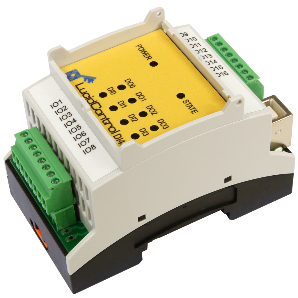
USB Digital Input Output Module
LucidControl Product Series
- 4 insulated digital input channels
- Counters, filters, edge detectors
- Pulse width modulation and timers
- 4 solid-state-relay output channels

USB Digital Input Module
LucidControl Product Series
- 4 / 8 digital input channels
- For 5V, 10V and 24V signals
- Opto insulated contacts
- Counters and edge detectors

USB Digital Output Module
LucidControl Product Series
- Opto insulated option
- 4 / 8 digital output channels
- Relay module option
- Pulse width modulation and timers
- Switching and power control

USB Analog Input Module
LucidControl Product Series
- Measurement range options
- 4 / 8 analog input channels
- e.g. 0-10 V or 0-20mA
- 14 bit resolution
- Acquisition of sensor signals

USB Analog Output Module
LucidControl Product Series
- 4 analog output channels
- Output range options
- e.g. 0 - 10 V or 4 - 20 mA
- 12 bit resolution
- 4 - 20 mA current interfaces
USB RTD Input Module
LucidControl Product Series
- 4 / 8 Pt1000 / Pt100 RTD channels
- Temperature range: +/- 180 °C, 360 °C
- 0.1 °C resolution
- Heat control applications
- Logging of temperatures
LucidIoT Modbus TCP/IP Server
The LucidIoT data acquisition and control module can acquire and control up to 16 analog and digital I/O signals.
The Modbus TCP/IP field-bus protocol based on top of the Modbus application layer uses TCP/IP protocol and Ethernet link layer instead of the serial transfer used by Modbus RTU or ASCII.
It is widely spread in the industrial automation industry. LucidIoT can operate as Modbus TCP/IP server and allows clients to connect to it.
In contradiction to other field-busses like Profinet, CAN or EtherCAT, a standard Ethernet connection is used and protocol specific hardware is not needed.
On the downside Modbus TCP/IP is not able to handle real-time tasks because the Ethernet link layer it not time deterministic, what means that synchronization can not be guaranteed. But, since LucidIoT does not claim being real-time this is not really important and Modbus TCP/IP is a great protocol interfacing LucidIoT.
Modbus TCP/IP is easy to understand and many libraries like pyModbusTCP for Python are available for different programming languages. Communication can be sniffed and recorded by free tools like qModMaster.
Many I/O signals like digital signals, relays, 5V, 0-10V, 24V voltages or 4-20mA currents can be measured and controlled by the Modbus TCP/IP protocol and LucidIoT.
Configuration of Modbus TCP/IP Server

The Connection section contains values that configure the Modbus TCP/IP server.
The module can be enabled here. If enabled the server is listening on the configured port (default 502).
The protocol can be enabled for IPv4 and/or IPv6 networks.
The configurable Keep Alive timer interval enables detection of inactive connections and releases their resources.
The State section gives information about the LucidIoT Modbus service.
If configuration was changed, the Reset flag indicates if a restart of LucidIoT is necessary.
Using LucidIoT Modbus TCP/IP
| Address | Register Description |
| 0x1000 to 0x101E | 32 Bit wide Holding Registers of I/O Channel Number 0 to 15 Values |
| 0x1100 to 0x111E | 32 Bit wide Holding Register of I/O Channel Number 0 to 15 Configuration Parameter 0 |
| 0x1200 to 0x121E | 32 Bit wide Holding Register of I/O Channel Number 0 to 15 Configuration Parameter 1 |
| 0x2000 to 0x200F | 16 Bit wide (Standard) Holding Register of I/O Channel Number 0 to 15 Values |
| 0x2100 to 0x210F | 16 Bit wide (Standard) Holding Register of I/O Channel Number 0 to 15 Configuration Parameter 0 |
| 0x2200 to 0x220F | 16 Bit wide (Standard) Holding Register of I/O Channel Number 0 to 15 Configuration Parameter 1 |
| 0x8000 | Start of internal registers e.g. System Time |
LucidIoT values are accessible as holding or input registers. The registers are stored in standard Modbus 16 bit wide representation and also in 32 bit wide representation combining 2 standard registers.
The standard registers have the advantage that they are defined in the standard, but they have limited value range. The 32 bit wide registers give much higher precision, but are supported by less other devices.
LucidIoT implements both, 16 and 32 bit wide registers. Starting at address 0x1000 with 32 bit wide registers, at address 0x2000 with standard 16 bit wide registers.
Modbus allows the client to access to the I/O Values which represent e.g. the analog voltage of an analog input channels.
Moreover, The I/O Configuration Parameters 0 and 1 can be accessed by Modbus protocol. This allows the client to change e.g. duty-cycle or period of a PWM output signal.