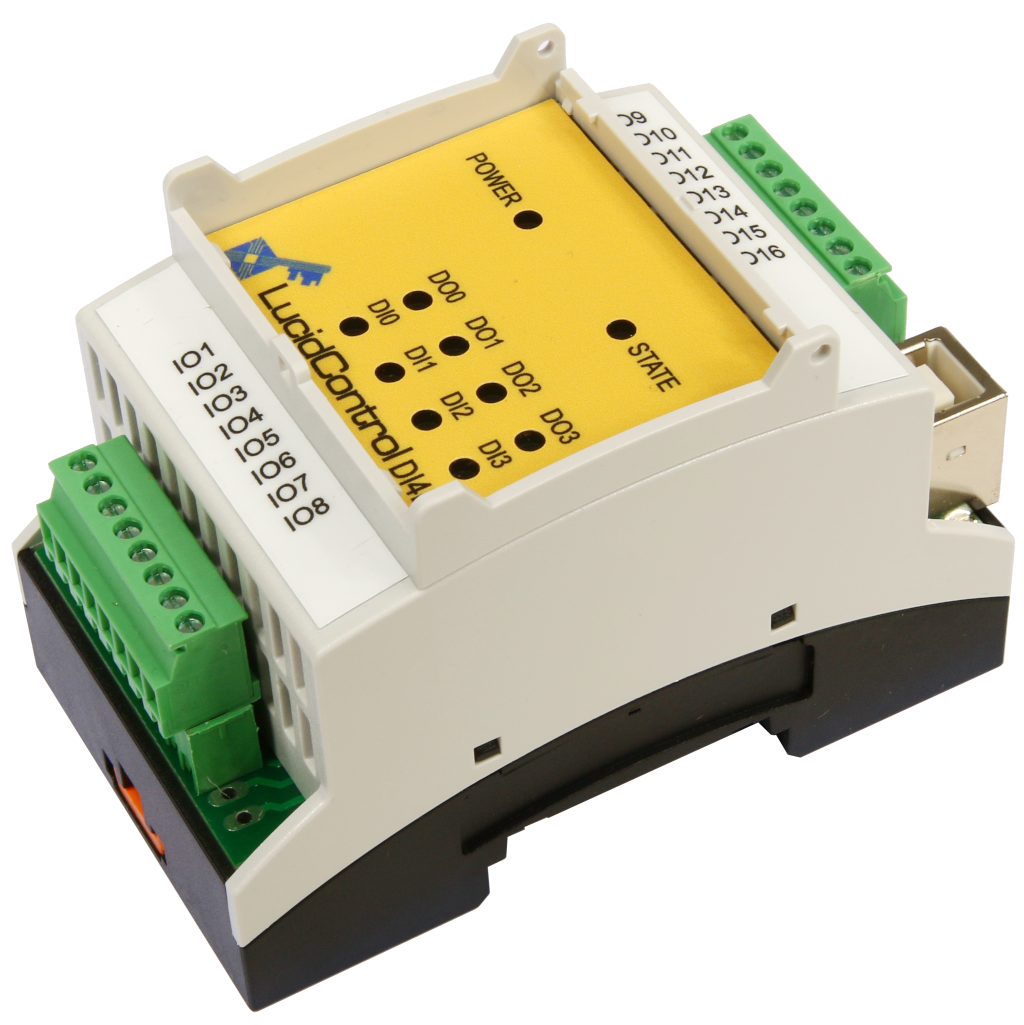
Configuration of LucidIoT Network Analog Outputs
The LucidIoT Ethernet network controller is a configurable data acquisition and control system. It can drive up to to 16 analog lines like 0-10V or 4-20mA. The signals can be accessed e.g. by MQTT protocol, Modbus TCP/IP protocol, web browser, or JSON interface via TCP sockets.
The LucidIoT network analog output module configuration controls 8/16 voltage or current signals. It operates with 0-10V and 4-20mA interfaces.
LucidIoT IO slots can be equipped with one or two analog output units providing up to 16 independent, programmable voltage or current sources.
The first group (IO slot 0 on the left side) provides its outputs at the connectors X1 and X2. In addition, the second group (IO slot 1 on the right side) has its outputs located at the connectors X3 and X4.
The two groups can have different ranges what means that e.g. 8 channels can supply 0-10V signals while the other 8 channels control 4-20 mA signals.
The analog output channels have a resolution of 12 bit with a typical accuracy of 0.25%.
Network Analog Output Module 0-10V Configuration
The picture shows the connection of the terminal IO of the Analog Output Module with a voltmeter connected to IO terminals 1 and 2.
The IO terminals 1, 3, 5 and 7 represent the positive voltage outputs, the IO terminals 2, 4, 6 and 8 are connected to ground potential.
Analog Output Module 4-20mA Configuration
The picture shows the connection of the terminal IO of the Analog Output Module with a current meter connected to IO terminals 1 and 2.
The IO terminals 1, 3, 5 and 7 represent the positive current outputs, the IO terminals 2, 4, 6 and 8 are connected to ground potential.
The output channels are made in order to source a 4-20mA current which is typically flowing through a 500 Ohm burden resistor.
Accessing IO Values with Web Browser
The web interface can access the IO values of the analog output channels by using a web browser.
Voltages are represented in millivolt, currents in microampere without decimals.


