

- 16 analog and digital IO channels
- HTTPS, Modbus TCP/IP, MQTT, FTP
- SSL/TLS secured
- Data logging function
- Compatible with LucidControl software
- DIN-Rail enclosure
- Multi-Protocol

LucidControl USB IO Modules
- Data acquisition and control
- Cost effective and flexible
- Platform independent
- Windows® and Linux
- Compatible with Raspberry Pi
- Clippable on DIN-Rail
- Industrial & home automation
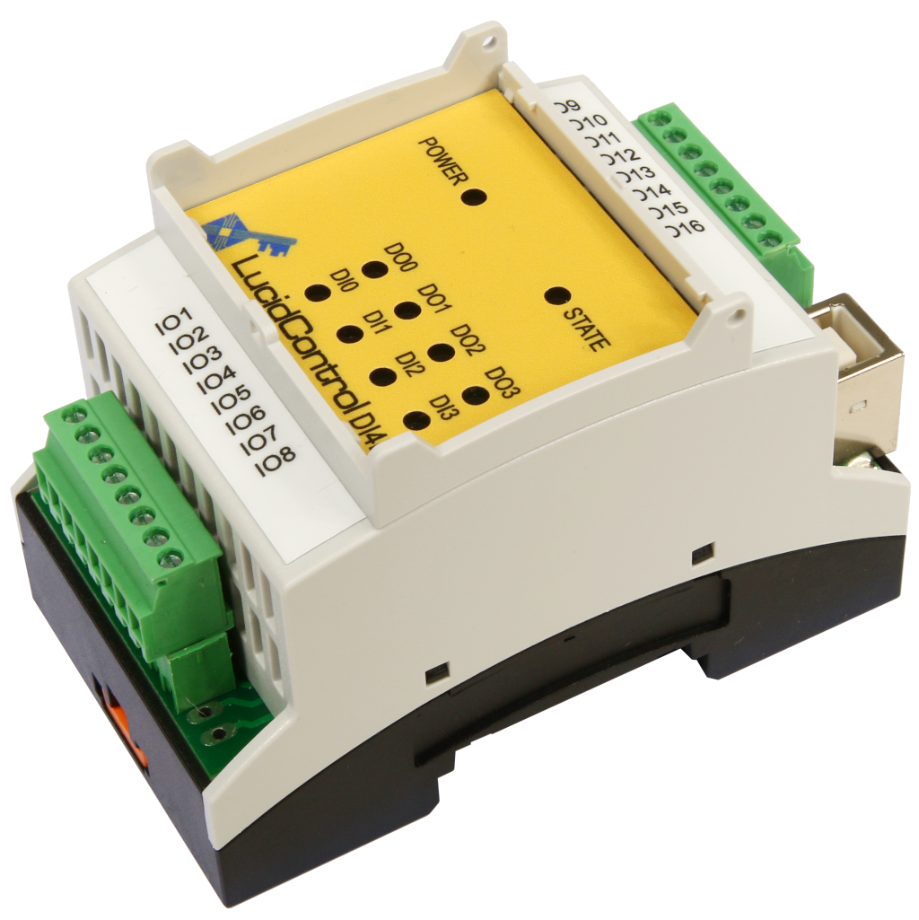
USB Digital Input Output Module
LucidControl Product Series
- 4 insulated digital input channels
- Counters, filters, edge detectors
- Pulse width modulation and timers
- 4 solid-state-relay output channels

USB Digital Input Module
LucidControl Product Series
- 4 / 8 digital input channels
- For 5V, 10V and 24V signals
- Opto insulated contacts
- Counters and edge detectors

USB Digital Output Module
LucidControl Product Series
- Opto insulated option
- 4 / 8 digital output channels
- Relay module option
- Pulse width modulation and timers
- Switching and power control

USB Analog Input Module
LucidControl Product Series
- Measurement range options
- 4 / 8 analog input channels
- e.g. 0-10 V or 0-20mA
- 14 bit resolution
- Acquisition of sensor signals

USB Analog Output Module
LucidControl Product Series
- 4 analog output channels
- Output range options
- e.g. 0 - 10 V or 4 - 20 mA
- 12 bit resolution
- 4 - 20 mA current interfaces
USB RTD Input Module
LucidControl Product Series
- 4 / 8 Pt1000 / Pt100 RTD channels
- Temperature range: +/- 180 °C, 360 °C
- 0.1 °C resolution
- Heat control applications
- Logging of temperatures
Outdated Information
This online document might be outdated. Please see the LucidControl USB Digital Input Module PDF documentation instead.
3 Module Operation
3.1 Input Modes
This section explains the operation of the different input modes of the LucidControl USB Digital Input Module and gives examples how to configure and use them.
Each of the inputs of the module can work in one of the following modes:
In all modes the input values are captured and evaluated after a stable signal has been detected.
Physical input value inversion:
Digital inputs distinguish between physical and logical input state. The physical state is represented by the voltage applied to the input. The logical state is calculated by the input handling and may be identical to the physical state.
In case of input inversion is enabled by setting inDiInverted to “on” the logical value is inverted in relation to the physical input. This means that applying a voltage above VHighMin results in a HIGH physical input value but a LOW logical input value.
All input modes support the inversion of physical input value, but in practice it is useful for Reflect Mode only.
3.1.1 Reflect Mode
Reflect Mode gives access to the logical input value directly.

Fig. 3.1.1-1 Digital Input Reflect Mode Processing
Fig. 3.1.1-1 illustrates the processing of the inputs in Reflect Mode.
As soon as the rising edge of the input signal is detected it must remain stable over the interval TScan. After TScan has passed the input signal is captured and the input value is set to the corresponding value.

Fig. 3.1.1-2 Digital Input Reflect Mode Pulse Width
In the case that a pulse is shorter than TScan the pulse is not valid. This scenario is shown in the first pulse of Fig. 3.1.1-2. While the first rising edge starts the scan timer the falling edge stops it (indicated by the gray TScan interval) resulting in canceling the pulse detection.
Since the second pulse is longer than TScan it is evaluated as valid value.
Filtering digital signals and validating their stability can be used to surpress errors and to make the recognition of digital inputs more relyable.
The scan interval TScan is configurable by changing the parameter inDiScanTime.

Fig. 3.1.1-3 Digital Input Inverted Reflect Mode
Fig. 3.1.1-3 illustrates the same input signal as Fig. 3.1.1-1 but with inDiInverted set to “on” resulting in logical input value being inverted in relation to the physical input value.
Since most operating systems and USB are not able to handle tasks in very short intervals (e.g. shorter than 10 ms) this is not reliable and pulses may be lost.
For such purpose edge detecting and counting modes provide more real time functionality without reading the input value permanently.
LucidIoCtrl Command Line Tool Example
Configure output channel 0 for Reflect Mode
LucidIoCtrl –dCOM4 –c0 –sinDiMode=reflect [ENTER]
Read input channel 0
LucidIoCtrl –dCOM4 –c0 –tL -r [ENTER]

->  CH0:00
3.1.2 Edge Detection
For applications with very short input signal pulses the module provides two edge detection modes. While in Rising Edge Mode the module is sensitive for input signal low-to-high transitions in Falling Edge Mode it recognizes high-to-low transitions.
Personal computers running Microsoft Windows® or Linux do not have a proper real-time behavior for detecting fast input signals correctly. Because of multitasking it cannot be ensured that a task will run within a specified interval. Assuming that short pulses (e.g. shorter than 1 ms) should be detected the computer has to read the input value at least 1000 times per second which is not realistic. Otherwise it is possible that a pulse is located between two readings of the computer and the pulse will be missed.
These two modes are useful in order to allow real-time detection of input signal transitions without the host computer being affected. Fig. 3.1.2.1-1 shows that a recognized pulse and the input value representing this pending event indicating that at least 1 transition occurred between two readings of the computer.
By changing parameter diInScanTime the length of the shortest detectable pulse can be adopted by changing scan interval time TScan.
Example
The input should be able to detect an input signal pulse of 100 µs length.
One would say it is sufficient to read the input in reflect mode every 50 µs (with safety time) in order to detect the transition by the computer. But probably the operating system of the computer would violate the timing restrictions and pulses are lost.
By using the input configured in one of the two edge detection modes this can be solved easily by setting TScan = 90 µs (including safety). A detected edge will be pending until it is read by the host computer. Assuming the host computer reads now every second it can check if one ore more transition(s) occurred within the last second. The 1 second interval can be realized by the host computer without problems.
LucidIoCtrl Command Line Tool Example
Configure output channel 0 for Rising Edge detection mode
LucidIoCtrl –dCOM4 –c0 –sinDiMode=risingEdge [ENTER]
Set TScan to 90 µs
LucidIoCtrl –dCOM4 –c0 –sinDiScanTime=90000 [ENTER]
Read input channel 0
LucidIoCtrl –dCOM4 –c0 –tL -r [ENTER]

->  CH0:01
3.1.2.1 Rising Edge Mode

Fig. 3.1.2.1-1 Digital Input Rising Edge Mode
Fig. 3.1.2.1-1 shows a digital input signal and the corresponding input value in Rising Edge Mode. After the high signal was detected as valid it is noticeable that the set input value is pending until the value is read by the host computer.
Rising Edge Mode allows detecting low-to-high transitions of the input signal without the host computer being involved.
3.1.2.2 Falling Edge Mode

Fig. 3.1.2.2-1 Digital Input Falling Edge Mode
For the Falling Edge Mode applies the same functionality as for Rising Edge Mode with the one exception that not a rising but a falling transition sets the input value.
While in Rising Edge Mode it is obvious that a low-to-high transition sets the input value to “1” it must be mentioned that in Falling Edge Mode a transition from high-to-low sets the input value to “1”.
This shows that the input value in edge detection modes does not refer the input signal rather than it must be seen as a pending event. When the event (which can be either a low-to-high or high-to-low input signal transition) arises the input value is set to “1”.
3.1.3 Count Mode
Compared to other modes the Count Mode is different by means that it does not generate an input value, but calculates the number of valid pulses accumulated within a time specified by TCount. This mode allows to count pulses and to calculate frequencies of periodical input signals.

Fig. 3.1.3-1 Digital Input Count Mode
Fig. 3.1.3-1 illustrates a typical periodical input signal. In Count Mode all detected pulses are accumulated until the counting interval TCount finishes.

Fig. 3.1.3-2 Digital Input Count Mode
Fig. 3.1.3-2 shows the identical input signal, but with a shorter counting interval.
After TCount has passed the valid count value is accessible and the module starts with a new measurement cycle.
Like in the other modes an input signal is only regarded as valid when it was stable for at least the scan time TScan. In Count mode only stable pulses are accumulated (see the gray interrupted TScan intervals).
Normally, TScan timer is started on the rising edge of the input signal as it is shown in the two pictures above. In the case that the parameter inDiInverted is set to “on” TScan timer is started on the falling edge of the input signal.
Accessing the input value in Count Mode returns the number of pulses of the last finished scan interval cycle.
LucidIoCtrl Command Line Tool Example
Configure input channel 0 for Count Mode
LucidIoCtrl –dCOM4 –c0 –sinDiMode=count [ENTER]
Set Scan Time TScan to 1ms
LucidIoCtrl –dCOM4 –c0 –sinDiScanTime=1000 [ENTER]
Set Count Time TCount to 1s
LucidIoCtrl –dCOM4 –c0 –sinDiCountTime=1000000 [ENTER]
Read number of pulses
LucidIoCtrl –dCOM4 –c0 –tN -r [ENTER]

->  CH0:0x0064 (100)
In this example 100 pulses of at least 1 millisecond length occured within a measurement interval of 1 second.
Since the input value (number of pulses) is updated after count time has passed it takes 1 second to update the value. Decreasing count time results in a faster update of the input value.
Note
While in other modes the value type “L” is specified, in Count Mode the value type must be set to “N”. LucidIoCtrl returns the value in hexadecimal and decimal format.
3.1.3.1 Count Mode Options
In standard Count Mode the counter value is valid after count interval TCount has passed and it overwrites previously detected pulses.
In order to count pulses of non-periodical input signals the module supports two additional options Flag Parameter inDiAddCounter and Flag Parameter inDiResetCountsOnRead.
In the case inDiAddCounter is set to “off” the number of currently counted pulses is used for update after TCycle has finished. Previously counted pulses are overwritten and get lost. In the case inDiAddCounter is “on” the number of currently counted pulses is added to the counter containing the pulses of previous measurements.
In the case of inDiResetCounterOnRead set to “off” reading of the counter value does not affect the counter value itself. In the case of inDiResetCounterOnRead is “on” the counter value is reset after reading it.
In order to avoid overflows inDiAddCounter=”on” should be combined with inDiResetCounterOnRead parameter.

Fig. 3.1.3.1-1 Digital Input Count Mode Options
Fig. 3.1.3.1-1 shows a typical input signal with 10 pulses in total which is not periodic. This diagram shows the behavior and the 3 read values for both, inDiAddCounter and inDiResetCounterOnRead switched “on” which is the most useful mode.
The number of counts in the diagram refers to the internal counter which may differ from the read number of counts by means that the read value is updated only after TCount has finished.
On Read 1 the read value is 2 since the internal counter value after TCount has finished was 2. The counter value is reset on reading and 1 pulse is carried over to the next TCount inverval.
On Read 2 the read value is 3 because of the current pulse counter of 2 plus the carried over counter value of 1 from the previous count interval. The counter value is reset on read.
At the reading 3 the read value is 3. And the counter value is reset again
This example explains that there are no pulses lost even if there is a longer time in between of subsequent readings.
Count mode with inDiAddCounter = “on”
In the case that inDiAddCounter is “on” and inDiResetCounterOnRead is “off” the behavior changes that the pulses are accumulated but the counter is not reset on reading the value. This causes the counter value is updated when count interval has finished and the current counter is added to the last counter value. This may result in an overflow when the counter value rolls over its maximum value of 65535.
The parameter inDiResetCounterOnRead has only an effect together with inDiAddCounter set to “on”.
The table below explains the different count value results of the previous example for all options.
| Mode | Value Read 1 |
Value Read 2 |
Value Read 3 |
|---|---|---|---|
| inDiAddCounter = “on” inDiResetCounterOnRead = “on” |
2 | 3 | 3 |
| inDiAddCounter = “on” inDiResetCounterOnRead = “off” |
2 | 5 | 8 |
| inDiAddCounter = “off” inDiResetCounterOnRead = “off” (Standard Count mode) |
2 | 3 | 2 |
3.2 Commands
After an input was set up correctly and configured it is possible to read the input value by using the commands GetIo for a single value or GetIoGroup in order to read a group of input values of the same type.
Accessing inputs and outputs is a very common task which is mostly identical for all LucidControl modules. Please refer to the sections:
- LucidIoCtrl Commandline Tool (Read Command)
- General Lucid Control Documentation (Implemented Commands)
The following sections describe in detail the commands which are supported by the DI4 module.
3.2.1 GetIo
This command reads the value of an digital input.
Please see also the General LucidControl documentation for more information.
This table illustrates the meaning of the values depending on the Input Mode.
| Mode | Value |
|---|---|
| Reflect | Contains the logic input value as “0x00” or “0x01” |
| Edge Detection | Represents edge detected event values “0x00” or “0x01”. The information remains pending until it is read |
| Count | Represents the number of valid pulses within count interval time within the range of 0 … 65535 |
| Command | GetIo | Access | Read | ||||
|---|---|---|---|---|---|---|---|
| Opcode | 0x46 | ||||||
| LucidIoControl Command Line Tool | |||||||
| Call (-tL) | LucidIoCtrl –d[COMx] –c[Channel] –tL –r |
||||||
| Return |
CHn:LL
|
||||||
| Call (-tN) | LucidIoCtrl –d[COMx] –c[Channel] –tN –r |
||||||
| Return |
CHn:NN
|
||||||
Request Frame
| OPC | P1 | P2 | LEN |
|---|---|---|---|
| 0x46 | Channel | Value Type | 0 |
| Value | Description | |||||||||
|---|---|---|---|---|---|---|---|---|---|---|
| Channel | Number of input channel (Range: 0 ~ 3) | |||||||||
| Value Type |
|
Response Frame
| Status | LEN | Data Field |
|---|---|---|
| Status | Size | Value |
In case of successful execution the command returns the value of the specified channel number.
In the case of an error the command returns Execution Status Code.
3.2.2 GetIoGroup
This command reads the values of a group of digital inputs of the same Value Type. See also For more information about reading of digital inputs.
Please see also the General LucidControl documentation for more information.
| Command | GetIoGroup | Access | Read | ||||
|---|---|---|---|---|---|---|---|
| Opcode | 0x48 | ||||||
| LucidIoControl Command Line Tool | |||||||
| Call (-tL) | LucidIoCtrl –d[COMx] –c[Channels] –tL –rChannels Comma separated list of channels e.g. –c0,1,3 |
||||||
| Return |
List of values sorted from lower to higher channels CHn:LL
|
||||||
| Call (-tN) | LucidIoCtrl –d[COMx] –c[Channels] –tN –rChannels Comma separated list of channels e.g. –c0,1,3 |
||||||
| Return |
List of values sorted from lower to higher channels CHn:NN
|
||||||
LucidIoCtrl Command Line Tool Example
Read input values of input channel 0, 1 and 3:
LucidIoCtrl –dCOM4 –c0,1,3 –tL –r [ENTER]

-> CH0:00  CH1:01  CH3:01
Request Frame
| OPC | P1 | P2 | LEN |
|---|---|---|---|
| 0x48 | Channel Mask |
Value Type | 0 |
| Value | Description | |||||||||||||||
|---|---|---|---|---|---|---|---|---|---|---|---|---|---|---|---|---|
| Channel Mask | Specifies the output channels to access
Values can be bitwise combined |
|||||||||||||||
| Value Type |
|
Response Frame
| Status | LEN | Data Field |
|---|---|---|
| Status | Size | Value(s) |
In case of successful execution the command returns the value of the specified channel number.
In the case of an error the command returns Execution Status Code.
Example of GetIoGroup Request
This request frame reads inputs 0, 1 and 3
Request Frame
| OPC | P1 | P2 | LEN |
|---|---|---|---|
| 0x48 | 0x0B Mask |
0x00 | 0x00 |
Channel Mask (P1) = 0x01 OR 0x02 OR 0x08 = 0x0B
Response Frame
For input 0 = “0”, input 1 = “1” and input 3 = “1”
Values in Data Field are in ascending order Channel 0, Channel 1, Channel3.
| Header Field | Data Field | |||
|---|---|---|---|---|
| Status | LEN | Value Channel 0 |
Value Channel 1 |
Value Channel 2 |
| 0x00 | 0x03 | 0x00 | 0x01 | 0x01 |
3.3 Parameters
LucidControl modules allow configuration by a set of System Configuration Parameters and IO Configuration Parameters.
The Parameters are accessible by using the SetParam command and GetParam command which are described the genreral LucidControl documentation.
The relevance of some parameters affecting the Digital Input module may depend on the operation mode.
3.3.1 inDiValue
This IO Configuration Parameter reflects the value or state of the input.
In Reflect Mode and Edge Detection Mode the parameter contains the input value as it can also be read by GetIo or GetIoGroup command.
If the input is configured in Count Mode this parameter is “0”.
| Parameter | inDiValue | Access | Read |
|---|---|---|---|
| Address | 0x1000 | ||
| Values | Input Value | ||
| Default Value | 0x00 | Parameter Type | 1 Byte unsigned |
| LucidIoControl Command Line Tool | |||
| ParameterName | inDiValue | Parameter Values | 0x00 or 0x01 |
| Call (Get) | LucidIoCtrl –d[COMx] –c[Channel] –ginDiValue | ||
LucidIoCtrl Command Line Tool Example
Read value of input channel 0:
LucidIoCtrl –dCOM4 –c0 –ginDiValue [ENTER]

->  inDiValue=0
Note
For normal operation it is recommended to use the GetIo function in order to read the input value.
3.3.2 inDiMode
This IO Configuration parameter configures the operation mode of the input.
| Parameter | inDiMode | Access | Read / Write | ||||||||||||
|---|---|---|---|---|---|---|---|---|---|---|---|---|---|---|---|
| Address | 0x1100 | ||||||||||||||
| Values | Input Mode
|
||||||||||||||
| Default Value | 0x00 | Parameter Type | 1 Byte unsigned | ||||||||||||
| LucidIoControl Command Line Tool | |||||||||||||||
| ParameterName | inDMode | Parameter Values | 0x00 or 0x01 | ||||||||||||
| Call (Set) | LucidIoCtrl –d[COMx] –c[Channel] –sinDiMode=[Value] {-p} {--default} | ||||||||||||||
| Call (Get) | LucidIoCtrl –d[COMx] –c[Channel] –ginDiMode | ||||||||||||||
LucidIoCtrl Command Line Tool Example
Set operation mode of input channel 0 to Count Mode and make the setting persistent.
LucidIoCtrl –dCOM4 –c0 –sinDiMode=count –p [ENTER]
Read the operation mode of input channel 0
LucidIoCtrl –dCOM4 –c0 –ginDiMode [ENTER]

->  inDiMode=count
3.3.3 Bit Parameter inDiFlags
This IO Configuration Parameter groups Bit Parameters which are represented by one bit e.g. having an “on” or “off” state only.
| Parameter | inDiFlags | Access | Read / Write | ||||||||
|---|---|---|---|---|---|---|---|---|---|---|---|
| Address | 0x1101 | ||||||||||
| Values | Consists of the following Bit Parameters
|
||||||||||
| Default Value | 0x00 | Parameter Type | 1 Byte unsigned | ||||||||
Note
The parameter inDiFlags cannot be accessed directly by using the Command Line Tool. The Bit Parameters can be used instead.
Note
When inDiFlags is changed by the SetParam command the current setting of inDiFlags should be read before updating it in order to prevent overwriting other Bit Parameters.
>3.3.3.1 inDiInverted
This Bit Parameter configures the inversion of the physical input value.
See input modes descriptions for more information.
| Parameter | inDiFlags | Access | Read / Write | ||||
|---|---|---|---|---|---|---|---|
| Address | 0x1101 | Bit Parameter | |||||
| Values |
|
||||||
| Default Value | Off | Parameter Type | 1 Bit | ||||
| LucidIoControl Command Line Tool | |||||||
| ParameterName | inDiInverted | Parameter Values | on / off | ||||
| Call (Set) | LucidIoCtrl –d[COMx] –c[Channel] –sinDiInverted=[Value] {-p} {--default} | ||||||
| Call (Get) | LucidIoCtrl –d[COMx] –c[Channel] –ginDiInverted | ||||||
LucidIoCtrl Command Line Tool Example
Enable inversion of physical input channel 0 and make the setting persistent.
LucidIoCtrl –dCOM4 –c0 –sinDiInverted=on –p [ENTER]
Read inversion of physical input channel 0
LucidIoCtrl –dCOM4 –c0 –ginDiInverted [ENTER]

-> inDiInverted=on
3.3.3.2 inDiAddCounter
This Bit Parameter controls how the counter value is updated after count interval time TCount has finished. It is relevant in Count Mode only.
In the case inDiAddCounter is “off” the number of currently counted pulses is used for update after count interval time TCount has finished. Previously counted pulses are overwritten.
In the case inDiAddCounter is “on” the number of currently counted pulses is added to the counter value of previous measurements.
In order to avoid overflows inDiAddCounter=”on” should be combined with inDiResetCounterOnRead parameter.
| Parameter | inDiFlags | Access | Read / Write | ||||
|---|---|---|---|---|---|---|---|
| Address | 0x1101 | Bit Parameter | |||||
| Values |
|
||||||
| Default Value | Off | Parameter Type | 1 Bit | ||||
| LucidIoControl Command Line Tool | |||||||
| ParameterName | inDiAddCounter | Parameter Values | on / off | ||||
| Call (Set) | LucidIoCtrl –d[COMx] –c[Channel] –sinDiAddCounter=[Value] {-p} {--default} | ||||||
| Call (Get) | LucidIoCtrl –d[COMx] –c[Channel] –ginDiAddCounter | ||||||
LucidIoCtrl Command Line Tool Example
Enable counter add on update for input channel 0 and make the setting persistent.
LucidIoCtrl –dCOM4 –c0 –sinDiAddCounter=on –p [ENTER]
Read counter add setting of input channel 0
LucidIoCtrl –dCOM4 –c0 –ginDiAddCounter [ENTER]

->  inDiAddCounter=on
3.3.3.3 inDiResetCounterOnRead
This Bit Parameter controls how to update the counter value after reading it. It is relevant in Count mode only.
In the case of inDiResetCounterOnRead is “off” reading of the counter value does not affect the counter value itself.
In the case of inDiResetCounterOnRead is “on” the counter value is reset after reading it.
| Parameter | inDiFlags | Access | Read / Write | ||||
|---|---|---|---|---|---|---|---|
| Address | 0x1101 | Bit Parameter | |||||
| Values |
|
||||||
| Default Value | Off | Parameter Type | 1 Bit | ||||
| LucidIoControl Command Line Tool | |||||||
| ParameterName | inDiResetCounterOnRead | Parameter Values | on / off | ||||
| Call (Set) | LucidIoCtrl –d[COMx] –c[Channel] -sinDiResetCounterOnRead=[Value] {-p} {--default} | ||||||
| Call (Get) | LucidIoCtrl –d[COMx] –c[Channel] –ginDiResetCounterOnRead | ||||||
LucidIoCtrl Command Line Tool Example
Enable counter reset on read for input channel 0 and make the setting persistent.
LucidIoCtrl –dCOM4 –c0 –sinDiResetCounterOnRead=on –p [ENTER]
Read counter reset setting of input channel 0
 LucidIoCtrl –dCOM4 –c0 –ginDiResetCounterOnRead [ENTER]

->  inDiResetCounterOnRead=on
3.3.4 inDiScanTime
This IO Configuration Parameter specifies the scan time TScan of the digital input.
TScan defines the scan time interval within the input signal must be stable in order to detect it as valid.
| Parameter | inDiScanTime | Access | Read / Write |
|---|---|---|---|
| Address | 0x1111 | ||
| Values | TScan in µs (micro seconds) 80 µs ≤ TScan ≤ 1 s |
||
| Default Value | 500,000 | Parameter Type | 4 Bytes unsigned |
| LucidIoControl Command Line Tool | |||
| ParameterName | inDiScanTime | Parameter Values | TScan [µs] |
| Call (Set) | LucidIoCtrl –d[COMx] –c[Channel] –sinDiScanTime=[Time] {-p} {--default} | ||
| Call (Get) | LucidIoCtrl –d[COMx] –c[Channel] –ginDiScanTime | ||
LucidIoCtrl Command Line Tool Example
Set TScan of input channel 0 to 1.5 s and make the setting persistent.
LucidIoCtrl –dCOM4 –c0 –sinDiScanTime=1500000 –p [ENTER]
Read TScan parameter of input channel 0
LucidIoCtrl –dCOM4 –c0 –ginDiScanTime [ENTER]

->  inDiScanTime=1500000
3.3.5 inDiCountTime
This IO Configuration Parameter specifies the count time TCount of the digital input in Count Mode.
The count interval specifies the time the pulses of the input signal are accumulated.
| Parameter | inDiCountTime | Access | Read / Write |
|---|---|---|---|
| Address | 0x1112 | ||
| Values | TCount in µs (micro seconds) 1 ms ≤ TScan ≤ 1 h |
||
| Default Value | 5,000,000 (5 s) | Parameter Type | 4 Bytes unsigned |
| LucidIoControl Command Line Tool | |||
| ParameterName | inDiCountTime | Parameter Values | TCount [µs] |
| Call (Set) | LucidIoCtrl –d[COMx] –c[Channel] –sinDCountTime=[Time] {-p} {--default} | ||
| Call (Get) | LucidIoCtrl –d[COMx] –c[Channel] –ginDiCountTime | ||
LucidIoCtrl Command Line Tool Example
Set TCount of input channel 0 to 10 s and make the setting persistent.
LucidIoCtrl –dCOM4 –c0 –sinDiScanTime=10000000 –p [ENTER]
Read TCount parameter of input channel 0
LucidIoCtrl –dCOM4 –c0 –ginDiCountTime [ENTER]

->  inDiCountTime=10000000
| Previous | Top | Next |
|---|---|---|
| 2 Setup and Installation | LucidControl USB Digital Input Module Content | 4 Specification |
Leave a Reply
Want to join the discussion?Feel free to contribute!